




PCB alkaline etching removes unwanted copper while preserving the circuit pattern. When the process drifts, manufacturers may find residual copper, narrowed tracks, uneven features, or precipitate in the etcher. These symptoms can resemble one another even when their causes differ, making an immediate change to conveyor speed or bath chemistry a poor substitute for diagnosis.
For process engineers, quality teams, and OEM buyers, the practical question is whether a correction restores both copper clearance and the required conductor geometry. A panel that looks clean can still fall outside its drawing requirements. This guide explains how to organize alkaline etching troubleshooting, distinguish chemistry problems from equipment and upstream defects, and request evidence that a supplier has controlled the cause. Process adjustments should follow the approved recipe for the specific etchant and machine.
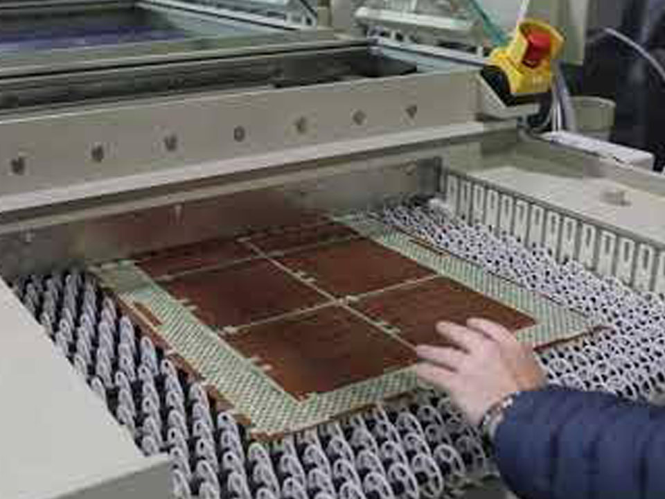
PCB alkaline etching commonly uses an ammoniacal copper chloride system. Ammonia complexes copper in solution, while the etchant dissolves exposed copper from the panel. Chemcut’s Process Guidelines for Alkaline Etching explains its compatibility with common metallic etch resists and identifies pH, copper content, chloride concentration, and temperature as interacting chemical controls. chemcut.net
A common application is outer-layer fabrication with a metallic resist protecting the desired features. However, layer type alone does not establish the correct chemistry. The approved process must account for the resist, copper construction, and equipment configuration.
Buyers comparing PCB products should therefore connect the required board construction to a documented fabrication route. Specifying an etchant name alone does not establish achievable conductor dimensions or production consistency.
Start by documenting where and when the defect appears. Identify the panel face, position, travel direction, artwork revision, and affected production interval. Preserve representative panels before rework changes the evidence.
Then compare incoming material, process records, and outgoing measurements. The following table is a diagnostic framework, not proof that any single symptom has one cause or a replacement for the supplier’s operating instructions.
| Observed problem | Investigation priority | Appropriate response direction | Evidence needed before release |
|---|---|---|---|
| Residual copper across much of a panel | Insufficient exposure, greater copper thickness, or reduced etch performance | Compare incoming copper, chemistry, and delivery with the qualified process before revising speed | Copper clearance and conductor dimensions both meet requirements |
| Isolated copper islands or bridges | Residual film, contamination, or unintended metallic resist shielding copper | Correct preparation or resist defects where confirmed | Before-and-after images at matching locations |
| Narrow tracks or excessive lateral loss | Excessive exposure, unsuitable compensation, or process drift | Identify the source of dimensional loss; avoid clearing copper at the expense of tracks | Dimensional results and representative cross-sections |
| Repeating bands or face-to-face differences | Uneven spray delivery, blocked nozzles, or transport-related shielding | Inspect spray patterns, manifolds, and rollers before a global recipe change | Uniformity results across positions and both faces |
| Crystals, sludge, or unstable bath behavior | Loss of chemical balance, replenishment failure, or unintended dilution | Contain affected work and obtain a chemistry-supplier disposition | Documented bath disposition and a qualified restart |
| Damaged protected features | Protective-layer defects or chemistry outside the approved compatibility window | Separate resist integrity problems from chemical compatibility | Feature integrity and relevant inspection results |
A useful first distinction is spatial versus temporal variation. A defect repeating at a machine location suggests a different investigation from a defect that develops progressively through a run. Treat these as clues to test, rather than automatic diagnoses.
Compare actual measurements with the current technical data sheet for the formulation in use. Avoid copying a pH, temperature, or density range from another plant’s recipe. Chemcut’s process guide includes different operating windows for different alkaline formulations, illustrating why one published range cannot serve as a universal specification.
Ask the process team to distinguish a controller reading from independent verification. Record the sampling time, sample location, measurement method, and instrument status. If a reading conflicts with observed behavior, resolve that discrepancy before making compensating additions.
MacDermid Alpha’s ammoniacal etchant guidance describes automated chemical monitoring as a means of maintaining a consistent operating state. For supplier qualification, the useful follow-up is how the plant verifies those readings and responds when control limits are exceeded. MacDermid Alpha
Three questions make a chemistry review more actionable:
Check the controls as a system: pH alone does not establish correct copper loading or chloride concentration, and a density reading does not independently identify every constituent. Compare temperature at the approved measurement point with its setpoint. A buyer need not prescribe chemical additions; require evidence that the supplier verified the full control window.
Residual copper should trigger two separate checks: whether exposed copper received adequate processing, and whether unwanted material shielded copper from the etchant. Extending exposure does not resolve every instance of incomplete clearance.
Compare the affected job with the qualified setup: copper entering the etcher, exposure conditions, process loading, and inspection results. Request measurements of the copper actually being removed, rather than relying exclusively on a nominal starting-foil description.
Also compare actual spray delivery with its qualified condition. A normal displayed pressure does not prove that every nozzle delivers the intended pattern. Inspect restrictions, leaks, and fluid supply where the defect map points to delivery problems.
If a revised exposure is proposed, judge it against two outcomes: clearance in the difficult areas and retained conductor dimensions elsewhere. Approval based only on the disappearance of visible copper leaves a dimensional question unanswered.
For defects confined to particular features, inspect preparation and masking at those locations. Compare images or retained samples from before etching where available. A targeted upstream correction is preferable when evidence shows that the intended copper surface was never properly exposed.
Use a defect map to prevent disconnected troubleshooting. Mark the same coordinates on the artwork, pre-etch record, and post-etch image. This helps engineering and the fabricator discuss a specific feature rather than exchanging broad descriptions such as “insufficient etching.”
If the issue requires a design change, a PCB layout review should address the affected features and fabrication constraints. Do not widen every clearance or alter every track before the root cause is established.
Undercut is lateral copper removal beneath the protective pattern. It must be evaluated separately from whether the spaces between features have cleared. Chemcut’s Thoughts on Undercut distinguishes undercut from etch factor and emphasizes the importance of defining the dimensions being compared. chemcut.net
Consequently, “our etch factor is acceptable” is incomplete evidence unless the supplier states the formula, measurement locations, and relevant acceptance criteria. Request a labeled cross-section and the actual dimensional results for the critical features.
The defensible process objective is a repeatable window in which clearance and conductor geometry are both acceptable. Maximum etch rate alone is an inadequate purchasing criterion. Faster processing may be commercially useful, but the comparison should include dimensional performance and the amount of acceptable output.
An illustrative example shows the decision. Suppose a trial clears the tightest spaces, but measurements reveal that another critical track is outside its approved width. The trial has resolved one symptom without satisfying the drawing. The next investigation should examine why the two requirements cannot be met together, including incoming construction, masking, uniformity, and compensation.
Any proposed changes to copper construction or critical geometry belong in the PCB design review. Record customer approval where a change affects the released design; do not treat manufacturing compensation as permission to revise electrical requirements.
Treat precipitation as a process excursion requiring investigation and disposition. In Maintain Alkaline Etchant: 5 Tips, Chemcut links low pH to sludge-out, warns that the precipitated copper-ammonia complex may not redissolve, and discusses chloride control and unintended dilution.
The same guidance explains a ventilation trade-off: airflow supports oxygen supply for regeneration, while excessive airflow can remove ammonia and lower pH. Ventilation therefore requires coordinated equipment and chemistry control; reducing extraction simply to recover a bath reading is not an appropriate independent remedy. chemcut.net
For an affected production lot, request a documented response:
The important commercial distinction is between a temporary return to an apparently normal reading and a controlled return to production. A clear bath or one passing panel does not, by itself, close the investigation.
Define success before running the confirmation trial. The acceptance criteria should identify the defect to eliminate, the dimensions to preserve, and the inspection coverage required. Otherwise, teams may approve a correction because it improves the most visible symptom.
For spatial problems, request measurements at the locations needed to challenge the suspected cause. A center-panel defect calls for evidence that includes the center. Face-to-face variation calls for measurements on both faces. Select locations and sampling with the supplier’s quality team rather than assuming a single convenient coupon represents the entire panel.
Match each inspection method to its question. Optical measurements assess accessible feature geometry; cross-sections reveal selected profiles; electrical testing checks specified connectivity or isolation. Passing one type of inspection should not be presented as proof that every other requirement has been met.
A useful corrective-action record includes the suspected mechanism, evidence supporting it, approved changes, trial conditions, results, and the prevention measure. State what remains uncertain if the evidence cannot isolate one cause.
For a PCB prototype build, specify which critical features need confirmation and whether the intended production route will be used. A prototype is more useful for qualification when its documentation allows a meaningful comparison with the later production process.
Evaluate the cost of acceptable boards delivered on schedule. A unit-price comparison becomes incomplete when one proposal leaves containment, repeat inspection, scrap replacement, or corrective trials undefined.
Ask suppliers to separate the cost and schedule effects of a design revision from those of a process correction. Also distinguish quoted manufacturing time from the time needed to approve new data or qualify a recovery. These details make competing proposals easier to assess without inventing a universal etching surcharge.
Useful questions include: Who authorizes reprocessing? Which results trigger rejection? How is affected work segregated? What evidence is supplied after corrective action? Are the reported yields for comparable construction and feature requirements?
When the order includes PCB assembly, establish the bare-board release criteria before component loading. This gives fabrication and assembly teams a shared acceptance point and clarifies responsibility if a board-quality concern emerges later.
Provide a package that connects the released design, the observed defect, and the required result. A photograph alone rarely establishes all three.
| Information to provide | Why it matters |
|---|---|
| Gerber or ODB++ data, drill files, and revision identifier | Establishes the manufacturing dataset and prevents comparisons between different revisions |
| Stackup, copper requirements, and relevant fabrication notes | Defines the construction the supplier must evaluate |
| Critical track widths, clearances, and agreed tolerances | Identifies the features that must survive any process correction |
| Board and panel details, with defect coordinates and orientation | Enables comparison between the design, machine position, and inspection results |
| Acceptance specification and required inspection records | Defines what constitutes successful qualification and release |
| Quantity, delivery needs, and trial-versus-production scope | Clarifies the commercial consequences of containment and qualification |
If a defect already exists, add the affected lot numbers, photographs with scale, inspection stage, measurement results, and relevant change history. Ask for a proposed trial and acceptance plan before authorizing a revised production run.
The practical next step is a joint engineering and quality review of that package. Agree on the evidence needed to release the boards, rather than asking only whether the fabricator can “improve the etching.”
No. Suitability depends on the approved chemistry, resist system, construction, and fabrication route. Alkaline etching is commonly associated with metallic-resist outer-layer processing, but buyers should verify the actual route instead of assuming all layers use the same process.
Use the operating range specified for the actual formulation. Published guidance covers different alkaline systems and does not establish one universal setting. Ask the supplier how pH is measured, independently verified, and controlled during the affected production interval.
It may help when inadequate exposure is the confirmed cause. It does not establish a solution for unintended masking or other localized defects. A trial must demonstrate acceptable copper clearance and retained conductor geometry before the revised setting is approved.
Do not assume so. Chemcut warns that the precipitated copper-ammonia complex may not redissolve. Obtain the chemistry supplier’s disposition, investigate the excursion, and qualify the restart rather than treating filtration as proof of restored chemistry.
No. Electrical testing addresses the connectivity or isolation covered by the test. It does not independently establish every conductor dimension or profile. Specify dimensional inspection and cross-sectional evidence where needed alongside electrical testing.
Usually, specify the required construction, finished geometry, electrical performance, and acceptance evidence. Require a particular chemistry when an engineering, qualification, or customer obligation justifies it. Otherwise, ask the fabricator to propose and substantiate a suitable process.


Learn how PCB impedance coupons, TDR measurements, tolerance limits, and traceable reports support fabrication acceptance and more accurate supplier RFQs.

Compare flying probe and bed-of-nails for bare multilayer PCBs, including electrical coverage, netlist control, probe access, fixture economics, and RFQ requirements.

Learn the differences between PCB surface preparation, wet processing, and final finishes, with practical guidance on plating terminology, inspection evidence, and RFQ requirements.